PCB Prototype the Easy Way
Full feature custom PCB prototype service.
9:00 - 18:00, Mon.- Fri. (GMT+8)
9:00 - 12:00, Sat. (GMT+8)
(Except Chinese public holidays)
PCB Prototype the Easy Way
Full feature custom PCB prototype service.
9:00 - 18:00, Mon.- Fri. (GMT+8)
9:00 - 12:00, Sat. (GMT+8)
(Except Chinese public holidays)
Thermal conductivity is a material property that describes the ability of a material to conduct heat after heat is transferred into it.Traditional PCB materials such as FR4 and Polyimide have low thermal conductivity coefficients,which are unable to meet the increasing thermal demands of high-power PCBs. Currently,one of the methods to address this heat dissipation issue is to use Metal Core Printed Circuit Board (MCPCB).
Metal Core Printed Circuit Board (MCPCB), also known as insulated metal substrate (IMS) PCB and thermal PCB,as opposed to traditional FR4,is a PCB based on a metal material used for the heat dissipation part.During the operation of a circuit board,heat is generated by certain electronic components.The purpose of the metal is to transfer this heat from critical board components to less important areas,such as metal heat sinks or metal cores.The most commonly used metals in MCPCB manufacturing are aluminum,copper and steel alloys.
Aluminum has good heat transfer and dissipation capabilities and is relatively inexpensive.Copper offers better performance but is relatively more expensive.Steel, on the other hand,can be divided into regular steel and stainless steel,it is harder than aluminum and copper but has lower thermal conductivity.
Users can choose their base core material based on different applications.Among all these metals,considering thermal conductivity, rigidity, and cost, aluminum is the most economical choice.Therefore,the core material of a standard Metal Core PCB (MCPCB) is made of aluminum.
MCPCBs consist of a conductive layer,a thermal insulation layer board,and a metal substrate layer.
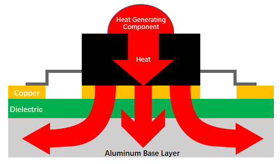
The Basic Structure of MCPCB includes:
Solder mask layer
Circuit layer
Copper layer 1oz. to 6oz. (most commonly used is 1oz. to 2oz.)
Dielectric layer
Metal core layer - heatsink or heat spreader
To learn more about thermoelectric separation technology,see Thermoelectric Separation Technology of Copper Core PCB
Metal core PCBs have some unique advantages over traditional FR4 PCBs, including:
• Superior heat dissipation:MCPCBs,utilizing a metal substrate such as aluminum or copper, offer excellent thermal conductivity.This allows MCPCBs to have effective heat dissipation in high-power and high-temperature applications,reducing the operating temperature of circuit components and enhancing system reliability and lifespan.
• Reduced reliance on heatsinks and other bulky hardware: In comparison to traditional fiberglass-based substrates,which have poorer thermal conductivity, MCPCBs can better meet heat dissipation requirements,reducing the need for additional hardware such as heatsinks.
• The durability of aluminum: Aluminum,in contrast to commonly used materials in PCB manufacturing such as ceramics and fiberglass,possesses higher strength and durability.It is a highly robust metal that helps minimize the risk of accidental damage during production stages,assembly processes,or normal usage of the final product.
• Lighter weight and higher recyclability:PCBs with metal substrates are lighter, longer-lasting, and exhibit better conductivity compared to traditional PCBs made with epoxy resin materials.Additionally,they are more environmentally friendly,as the metals used (including aluminum) are non-toxic and easily recyclable.
• Dimensional stability:Metal-based printed circuit boards exhibit greater dimensional stability compared to PCBs made with traditional materials like FR-4,as environmental conditions change.Through heating processes ranging from 30°C to approximately 150°C,PCBs with metal layers (such as aluminum) experience minimal dimensional changes, typically ranging from 2.5% to 3.0%.
Based on the different positions of PCB metal core and trace layers,MCPCB can be classified into five basic types:
Single layer MCPCB (only one trace layer on one side)
COB MCPCB (chip-on-board MCPCB, one trace layer)
Double layers MCPCB (two trace layers on the same side)
Double-sided MCPCB (two trace layers on each side)
Multi-layers MCPCB (more than 2 trace layers per board)
It consists of a single copper conductive layer, a metal substrate (such as aluminum),and a dielectric layer as an insulator.

Single Layer MCPCB Structure
Applications
Audio devices:The pattern inside the single-layer PCB provides mechanical strength and offers thermal efficiency in various audio devices.
Relays (automotive and industrial):The automotive industry utilizes thermally conductive PCB boards as they require prolonged operation at high working temperatures while maximizing space utilization.
LED lighting:Single-layer PCBs ensure the lowest possible operating temperature and maximum brightness for LED bulbs and devices.
Sensor products:The high thermal conductivity allows for quick and efficient heat transfer, making it suitable for various sensor products.
Packaging equipment:Single-layer metal-based PCB boards can be treated with organic surface protectants (OSP),immersion silver, tin,and gold,enhancing their efficiency.
COB MCPCB (Chip-on-Board Metal Core Printed Circuit Board) features microchips (also known as bare dies) that directly contact the metal core.The metal core dissipates heat and provides electrical interconnections with the circuit board's traces (wire bonding),thus supplying power.
In conventional MCPCBs,there is a dielectric layer between the copper traces and the metal core,limiting the thermal conductivity to a range of 1 to 3 W/m.K.However,with the use of COB MCPCB,as the dies directly contact the metal core,there is no such dielectric layer,resulting in the thermal conductivity of COB MCPCB being almost the same as that of the metal core material itself.
The typical material for the metal core is aluminum,so the thermal conductivity of COB MCPCB exceeds 200 W/m.K.
The COB process for chip packaging (Chip-on-Board) includes three main steps:
Chip mounting or chip bonding
Wire bonding
Encapsulation of the packaged chip
By utilizing wire bonding and epoxy resin encapsulation,followed by direct embedding onto the MCPCB, the lifespan of LEDs can be extended,and uniform light emission can be achieved.
Based on the process and materials used, COB MCPCB applications can be divided into two categories:mirror-finished aluminum with silver or gold plating,or silver mirror-finished aluminum PCB.
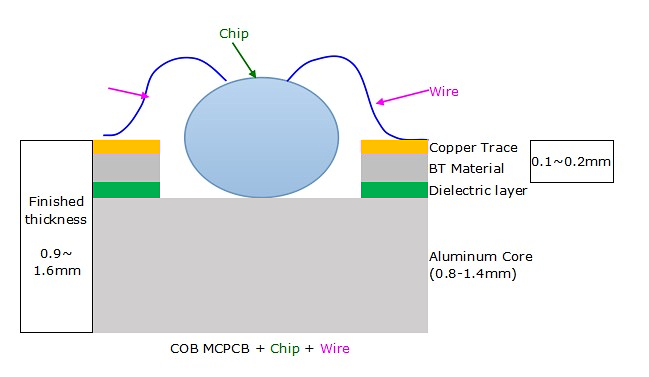
COB MCPCB Structure
Applications
Electronic lighting fixtures
High-power LEDs (up to 200W)
Power supplies• LED backlighting for LED TVs
Automotive applications
LED headlights for e-books
Street and parking lot lighting
Agriculture and horticulture lighting
Other products requiring thermal management solutions
A two-layer MCPCB consists of a metal core (usually made of aluminum or copper) and two copper conductive layers on the same side. The metal base is located at the bottom of the entire MCPCB, unlike a double-sided MCPCB where the two copper layers are placed on each side of the metal core. The assembly can only be done on the top surface.
In contrast to a single-layer MCPCB, a two-layer MCPCB requires an additional lamination step to bond the thermal conductive layer and the metal core (also known as the metal substrate) together. This structure requires more technical expertise and experience compared to regular FR4 PCBs to laminate the two layers with the metal core.
The processing steps of embedding the metal base in the MCPCB are more complex, as after drilling holes on the metal base, it is necessary to fill the holes to isolate it from the circuit.
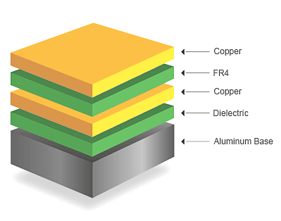
Double Layer MCPCB Structure
Applications
Office automation equipment
Power modules,such as power rectifiers, inverters, etc
Audio equipment,such as balanced amplifiers, preamplifiers, etc
Power controllers and electronic regulators in automobiles
Communication electronic devices,such as transmitter circuits and high-frequency amplifiers
Similar to two-layer metal-based PCB, double-sided metal core PCB also has two layers of copper conductors, but the metal core is positioned between the two conductors. Therefore, there are conductors (traces) on both sides of the metal core, and they are interconnected through vias. Hence, it is called "double-sided metal core PCB," and you can mount SMD components on both the top and bottom sides.
Unlike single-sided metal-based PCB, double-sided metal core PCB requires an additional lamination step to bond the patterned thermal conductive layer onto the metal core (also known as the metal substrate). However, sometimes, certain raw material suppliers for metal coverings provide pre-laminated sheets.
Compared to regular FR4 material, this structure requires more technical expertise and experience to laminate the two layers with the metal core.
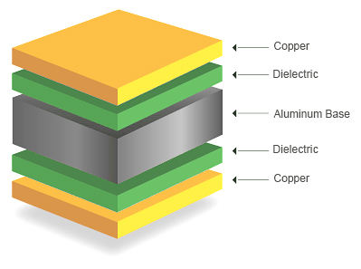
Double-Sided MCPCB Structure
Applications
Line Reactor
Industrial Control
Regulator
Power Supply
Converter
HVAC System
Hard Disk Drive
Automotive Dashboard
Transportation System
UPS System
A multi-layer MCPCB consists of two or more conductive layers separated by the thermally conductive dielectric material. At the bottom of the structure is the metal substrate, and SMT components can only be placed on one side. The use of THT components is not allowed, but it provides the possibility of manufacturing blind vias and buried vias with internal signal layers and power or ground planes.
Compared to regular FR4 material, this structure requires more technical expertise and experience to laminate the multiple layers of traces with the metal core. Additionally, the cost is much higher than that of a two-layer MCPCB or a double-sided metal-based PCB.
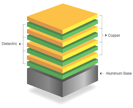
Multi-layer MCPCB Structure
Applications
File server
Weather analysis device
Particle accelerator
Nuclear detection system
Heart monitor
Fiber optic sensor
Satellite system
Signal transmission system
Satellite system
MCPCB, Metal Core PCB, thermal PCB Samples show >>
As our production capacity will always be upgraded and improved, in order to ensure the latest information Capability of MCPCB you can go to the PCB Instant Quote page to Check.