|
PLA Filament |
x 1 | |
|
|
ArduinoNano |
x 1 | |

|
Micro SD Card Module Slot Socket Reader |
x 1 | |

|
servomotor |
x 2 |

|
fusion360 |
|

|
arduino IDEArduino
|
|

|
MIT App Inventor 2 |
|

|
PrusaslicerPrusa
|
Skyviewer: a new way to look at the sky
INTRODUCTION
What is the Skyviewer
The Skyviewer is an autonomous, portable stand for phones that can reliably orient the camera phone to take perfect shots of any constellation without fancy equipment or expansive cameras. It in fact works mainly with phone sensors, however without losing in personalising, as the star catalogue is fully changeable, as I will cover later in this section. I had the idea during the final of the Italian astronomy championship, where I started getting into rudimental astrophotography, made only with my phone. I however found it quite frustrating not having the possibility to decide the orientation of the camera and so I started working on a stand, initially thought as manual and later developed in an automatic system, based on an Arduino nano. In this presentation I will cover the various aspects of this project, starting with a more insightful presentation and after describing its technical aspect.
How to use the Skyviewer
The Skyviewer is thought of as a simple, easy to use system. Look for the User guide for more information.
In order to interface with the phone, you will need an app, developed in the MIT AppInventor environment. While choosing the object, it is possible to quickly compare a small stellar map and a list of the constellations available by default in the “STAR” page. More information about the Skyviewer App is available on the Code and app section.
As mentioned earlier, one of the main features of the Skyviewer is the possibility to easily change the information contained in the star catalogue. The data of the default catalogue are available in the attachmetns, in the folder "catalogue". By default there are available only the main constellations of the boreal hemisphere, but more objects can be added. Here is a quick tutorial on how to add or change the catalogue. The meaning of the right ascension and the declination will be more clear after the following section. The catalogue is stored in three CSV files into an SD card, read by the Arduino via a reader. The files contain the following information of the objects: their name, theri right ascension and their declination. To add any object it is necessary to add in the file named “data.csv” the name of the object and in the respective line in the files named “DC” and “AR”, respectively, its declination (in decimal degrees) and it's right ascension (in decimal hours). It is important not to change the name of the files, as they need to be recognised by the Arduino. There is an example to add the galaxy M31 (Andromeda Galaxy).
In any online catalogue (in this example I used Stellarium), I search for the right ascension (AR) and the declination (dec) of the object. In this case AR = 0h 44m 6s, dec = 41° 24’ 33’’. I then converted the coordinates in decimal numbers, so AR = 0.735 h and dec = 41.41°. In the SD card, in the file “data” I added the object “M31”

Then in the files “DC” and “AR” in the same line (line 19) I inserted the respective coordinates

After saving, in the Skyviewer app the object “M31” appears in the 19th position.
In the following sections I will cover in detail more technical aspects of the Skyviewer, from the maths behind it to the mechanical challenges.
A BIT OF THEORY
Altazimuth and equatorial coordinates
Mathematically speaking, the main problem to resolve is determining the pitch (the rotation around the Y axis) and the yaw (the rotation around the Z axis) angles, starting with some information about the target star and about the actual time.

To achieve that, it is important to understand how the position of stars is tracked. At first, the coordinate systems used for stars are different from the normal Cartesian space used in classical mechanics, because of the inner nature of the celestial sphere, that, as the name suggests, is spherical, due to optical reasons outside of the scope of this presentation. So, as from any point internal to the sphere a point on the sphere surface can be detected by two angles, any celestial coordinate system uses only two variables. To be defined, any system needs a reference plane and a perpendicular (or, in other words, a defined point of the space used to refer to the star's position). The simplest system is the Altazimuth one. As a reference plane it uses the horizon plane, and as a straight line the perpendicular to the horizon that meets the observer. In this system, the position is expressed with azimuth (A) and altitude (h). The azimuth is the angular position of the star projection on the horizon taken by the Southern Meridian, while the altitude is the angular position on the sphere taken by the horizon plane.

Altazimuth coordinates
Another common system uses the equatorial coordinates. In this system reference planes and lines are commonly set for any observer of the world. The equatorial plane (the plane in the celestial sphere that meets the equator) is used as reference, as for (inserire dettagli sulla retta di riferimento). In this way, the reference point of the system coincides with the Gamma point.

The Gamma point and the reference plane of the equatorial system
The two coordinates used in this system are the declination (δ) and the right ascension (α), two angles that describe the position relative to the point on the sphere (the Gamma point) and not to a particular observer on earth. The hour angle (H) is defined as the complementary angle of the right ascension.

The equatorial system
Declination, azimuth and altitude are measured in degrees, right ascension and hour angle in degree-hour (every 15° are equivalent to an hour). It is possible to switching between the two units of measurement with the equation:

By this brief description it is easy to observe how for mechanical purposes the altazimuth system is more simple, but it has the important downside of not being invariant to space or time translation. This means that the position of a star in this system changes endlessly both in time and in space (so it is not uniquely defined for every point on earth). This means that a system which implements altazimuth coordinates should need an excessive number of data for every star (for any position on earth it should store the position for lots of days), resulting in an hugely inefficient system. Conversely, the equatorial system is more difficult to implement, but it has the advantage to have uniquely coordinates for every star, which can be tracked only with declination and right ascension (from now on, respectively δ, α). So, the main problem to resolve is to track the position with equatorial coordinates and ultimately evaluating its altazimuth coordinates.
Spherical triangle and Gauss equations
The problem is a matter of curve geometry, in particular of spherical geometry. In this sense, the coordinates of the two systems have to be interpreted as sides of a spherical triangle.
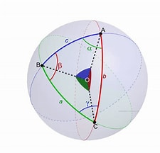
Spherical triangle of sides α, β, γ
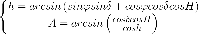
The mathematics developed in this field is the curve equivalent of trigonometry and the triangle can be resolved by using some equations, called the Gauss’ group equations:

where:
- h: altitude
- A: azimuth
- H: hour angle
- δ: declination
- φ: latitude
The first group equations allows to determine azimuthal coordinates by knowing the equatorial coordinates, the coordinates of the observer (measured as latitude and longitude) and the sidereal time (a particular measure of time typical of a certain place):
Latitude, longitude and sidereal time can be evaluated with the phone GPS and time data. O tried to directly implement the solution shown but I registered substantial error in the result, which might have been caused by the sidereal time function, which was far from precise. In the end, I used the library from David Armostrong “Sidereal Planets”, More information is available on github.
FEATURES AND MECHANICAL DESCRIPTION OF THE ASSEMBLY
The Skyviwer is an autonomous stand capable of two main movements, pitch and yaw. These two rotations are achieved with two servo motors. The final design is the product of different iterations, that allow a good balance between compactness and complexity. For the yaw a continuous servo is used. Such sensors do not have any control on the position, but they give the same mechanical characteristic of a common servo motor. In order to evaluate the position, the servo is coupled with a potentiometer. As many potentiometers are restricted to move from 0° to 180°, in order to evaluate the position on a complete rotation, the coupling is made with a transmission rate of 2:1 (every rotation of the motor corresponds to half rotation of the servomotor.) In this way, I can use an inexpensive potentiometer to read any effective angle.
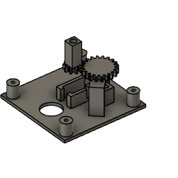
The coupling gears and the case of the mechanism.
For the pitch movement I opted for a normal 180° servo motor. In this case, the high mass of a phone (relative to the 9g torque of the servo) corresponds to a high moment of inertia that has to be compensated with a pretty high mechanical advantage. In fact, the center of inertia of the phone is about 7.5 cm higher with respect to the rotation axis. So, from theHuygens–Steiner theorem the moment of inertia around the pitch axis is about 6 times higher than the minimum possible.
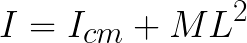
(where I is the moment of inertia, Icm is the moment of inertia around the center of mass and M and L are, respectively, the mass of the phone and the distance between the phone cm and the rotation axis)
By the theorem it is obvious how the inertia could be reduced by matching the rotation axis with the center of mass of the phone, but with a considerable cost in compactness. In the end, the best choice was to gain mechanical advantage by the coupling. This affects the maximum rotation, which is restricted to 45°. However, this is not a real limitation, as the high field of view of cameras allows the observation also of stars with an altitude greater than 45°
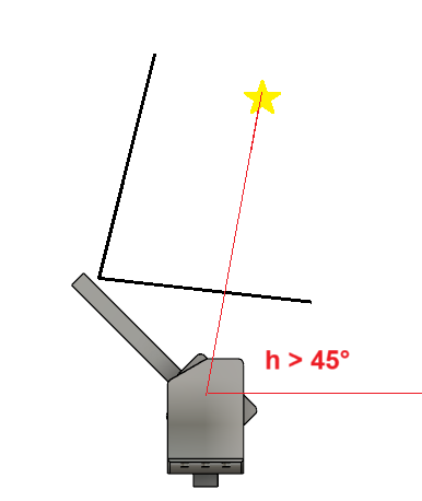
Behaviour for a star with an altitude greater than 45°
The servomotor is inside the stand, and is coupled with one of the support arms with an internal gear. The mechanical advantage is achieved with a gear ratio of 4:1.
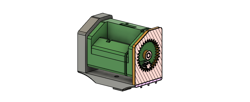
Section with external and internal gear (highlighted respectively in yellow and white). The internal gear is connected with the servomotor and the moving stand (in green).
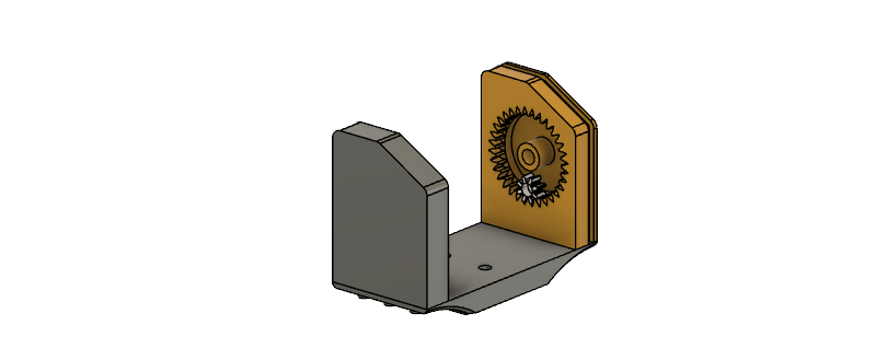
Representation of the internal and external gear, along with the other parts of the support (in grey).
For an insight on how to build the Skyviewer, please see the Assembly guide.
Features
The Skyviewer has some features that can help in the setting phase and in the shooting session. As it was thought to be portable, it can be used also in discontinuous surfaces, thanks to four adjustable supports, which can level the Skyviewer, in order to keep it parallel to the horizontal. If the four supports are not enough, there is also an mount for a tripod. The phone is secured with a tripod grip, attached to the stand (the green parts in the photo) with a quick release system. In this way, it is possible to switch easily between the Skyviewer and the tripod, in order to have a full range of liberty and comfort. The release system is easily adaptable to every grip, as it is only held in position with a M3 screw (which, however, is sufficient to keep the phone stable). the SD reader is exposed. In this way the SD card is easily accessible and the catalogue can be changed without opening the Skyviewer.
There is the possibility to integrate a power system, with a 18650 battery and a module for recharging (there is a dedicated space to keep the module and the pins to attach the system in the PCB, see the PCB section for more).
THE PCB
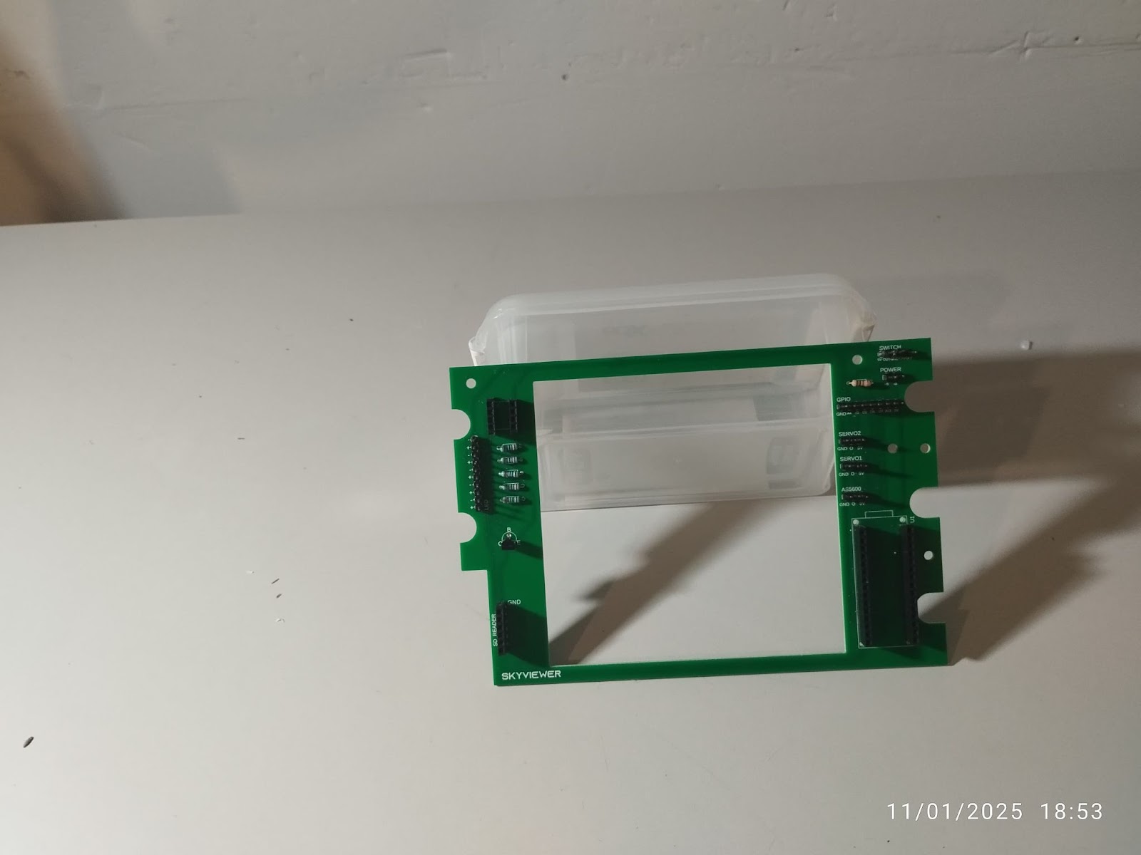
In order to keep all the electronics organised I designed a PCB I later ordered by PCBWay. If you are considering replicating this project I advise to use the PCB, as it simplified the connection among all the components. There is also space for an ATtiny 85 which can manage some LEDs, which can help signal the Skyviewer to prevent any accidental damage. Three leads are connected in parallel and are controlled by the same pin via a transistor. In this way maximum power is guaranteed to all the LEDs. The PCB visible in the photos has some minor errors, corrected in the version attached below. All the schematics and Gerber files are available below.
CODE AND APP
To interface the phone with the Skyviewer, I developed an app with MIT AppInventor. The app is available as a .apk in the attachments. The source code is available as a .aia file, usable in MIT AppInventor. The app has an incorporated list of the constellations initially available. Note that the list does not change as the catalog is changed.
Here is a brief explanation of the arduino code. In the setup() the Arduino initializes the object “myAstro”, which manages the astronomical calculations. Then, it takes various information (e.g. latitude and longitude, date) by the phone with the function getData(). The information is passed as a string, and the various variables are separated with a ‘;’ character. The parseFloat() method is used to separate the variable.
lat = Serial.parseFloat();
lon = Serial.parseFloat();
year = Serial.parseFloat();
month = Serial.parseFloat();
day = Serial.parseFloat();
hour = Serial.parseFloat();
minutes = Serial.parseFloat();
seconds = Serial.parseFloat();
Then, myAstro is updated with the various informations:
myAstro.rejectDST(); myAstro.setTimeZone(1); myAstro.setLatLong(lat, lon); myAstro.setGMTdate(year, month, day);
The main part of the loop() is managed with a switch case loop of the variable “stato”. Beforehand, the arduino checks for any activity on the phone, which is communicated through the serial.
if(Serial.available() > 0){
  char ch = Serial.read();
  if (ch == '0'){  }
  else if(ch == 'a'){
    button1 = true;
  }
  else if(ch == 'b'){
    button2 = true;
  }
  else if (ch == 'c'){
     button3 = true;
  }
  else if (ch == 'y'){
     STATO = true;
  }
}
In case 0, the user selects the constellation. Arduino, search for the name of the constellation related to the corresponding value of the variable “selectedC”, which is changed by the phone, and communicate to the app the name found.
Serial.println(Value);
After the constellation is selected, in case 1 the arduino extracts from DC.csv and AR.csv declination and right ascension of the selected object.
bool result = readCSVLine(file, lineNumber, value); if (result){ dec = value; } bool Result = readCSVLine(file, lineNumber, value); if (Result){ AR = value / 15.0; }
Then, myAstro is updated and elevation and azimuth are evaluated.
myAstro.setRAdec(AR, dec); myAstro.doRAdec2AltAz(); A = floor((myAstro.getAzimuth() ) * 1023/360); h = myAstro.getAltitude();
In case 2, 3 the Skyviewer moves the phone in the position evaluated. A while loop is used for controlling the yaw movement, moving the servo until the potentiometer value meets the azimuth evaluated:
while (analogRead(A0) < A){ servo2.write(30); delay(30); servo2.write(90); delay(30); }
A for loop is used to move smoothly the 180° servo:
for (int i = 180; i > 180-(4*h); i -=2){ servo1.write(i); delay(7); }
After the photo has been taken, the Skyviewer returns to its original position, the state returns to 0 and the case loop restarts.
DESIGN
For this project, I wanted to create a more complete object and so I decided to focus not only on the functionality aspect, but also on the aesthetics, which, however, are in service of the first ones . Every element, so, has a meaning and only small parts are specifically thought of as fully aesthetic components. While thinking about the Skyviewer’s curve I considered limiting the curve elements, in order to highlight the ones remaining. So, I ended up with a single, but double-centered, curve, which in the end highlighted the whole part of the stand, noting its importance in the Skyviewer.
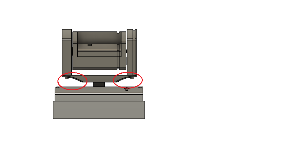
In red, the only curve is highlighted.
This principle can be seen in various architectures, like in the Guggenheim in New York. There, only one element is curved, and it is further highlighted by the straightness of the other elements which compose the museum.

I also took inspiration from the Renaissance architectures, in particular the one of Brunelleschi, where all the work was built around a common “module”, which dictate all the other elements.

The Brunelleschi “Hospital of Innocents” is a classic Renaissance example.
In the following image is highlighted the importance of the module, which rules the whole architecture.
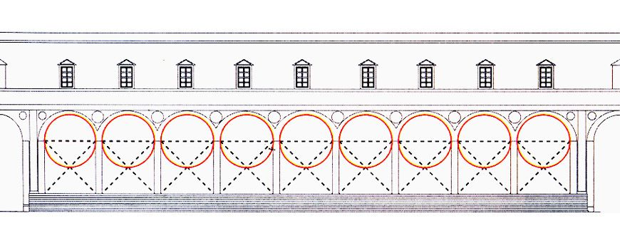
Usually, as can be seen in the example, this module was represented by a length (in this case the radius of the arch), but in my case I opted for a polygon, the 30-60 right triangle. This was opted for giving a bit of movement in the design, without losing coherency and minimalism, which I think is at the foundation of any modern technology product.

In red, the oblique elements (that stands for the 90-30-60 right triangle) are shown.
Along with it, in some places a bevel of radius 5 mm, which contributes also in giving unity to the Skyviewer.
FURTHER IDEAS
This is only the first version of Skyviewer, which will receive an update in the future. The next version will have BLE compatibility, to communicate more easily with your phone, a more usable app, which will manage all activities (for example take the photo with the best settings). The app will also turn the Skyviewer into a multifunctional stand, useful for landscape photography as well.

Skyviewer: a new way to look at the sky
*PCBWay community is a sharing platform. We are not responsible for any design issues and parameter issues (board thickness, surface finish, etc.) you choose.


- Comments(0)
- Likes(5)
 Log in to post comments.
 More by Antonio Antonio G.

-
-
Instrumentation Input, high impedance with 16 bit 1MSPS ADC for SPI
233 0 0 -
RGB LED Matrix input module for the Framework Laptop 16
427 0 2 -
-
-
-